| Support Center Items |
 What are 'Race Tools'? An Introduction What are 'Race Tools'? An Introduction |
Woolich Racing’s ‘Race Tools’ products provide your bike with additional capabilities designed for the race track.
There are five core Race Tools products that we offer: Quickshifters, Autoblippers, Pit Speed Limiter, Engine Warm-up and Launch Control. Not all models have Race Tools products available, and not all Race Tools products will be available on all models. To install Race Tools on your motorcycle, you will need to have the Race Tools key activated on your ECU, with a Woolich Racing flash.
Quickshifters and Autoblippers Quickshifters and Autoblippers both use a load sensor on the shift rod, but refer to two different operations.
A Quickshifter allows the bike to shift up in gears without needing to use the clutch or roll off the throttle by either cutting ignition or cutting fuel to the engine.
An Autoblipper allows the bike to shift down in gears without using the clutch, or without having to open the throttle manually by using the bike’s ETV (Electronic Throttle Valve) to 'blip' the throttle for you.
An Autoblipper is only possible on models that use a ride-by-wire throttle, ie. the throttle is controlled electronically by the ECU. This is common on most modern motorcycles, and allows the combination of Quickshifter and Autoblipper in a single product. If the bike uses a cable throttle, it can only be offered with a Quickshifter (ie. no Autoblipper possible).
We have two different sensors for the Quickshifter product; the GP Switch sensor, which is for Quickshifter-only models, and the GP ASG analogue sensor, which is for models that offer both the Quickshifter and Autoblipper.
Woolich Racing Quickshifter + Autoblipper Sensor
Launch Control Launch Control (LC) can be used as part of a Race Tools Package, or purchased as a standalone key. Depending on the model of bike there are different adjustment possibilities. Launch control is activated when the bike is stationary in first gear with the throttle closed, with the clutch in, and when the launch delay time has been reached.
When using Launch Control, it is important to remember that you still need to control the clutch, and that LC will not prevent a motorcycle from lifting the front wheel.
Pit Speed Limiter The pit speed limiter places a predefined limit on the RPM of the engine when the button is activated. This function requires the purchase of the additional pit speed limiter harness, and also requires a Race Tools key in order to activate it. The pit speed limiter is activated via this button when the bike is in 1st gear. For some models a standalone pit speed limiter and key are also available for purchase.
Pit Speed Limiter harness
Engine Warm-up Engine Warm-up is only offered on bikes that use an Electronic Throttle Valve (ETV) and is controlled using the Pit Speed Limiter button. Engine warm-up is activated when engaging the button while the bike is in Neutral.
RaceTools products availability for different models To find out what RaceTools products are available on different models, go to the Products page on our website, select the model and year, and scroll down to the RaceTools section. If we do not have any RaceTools products for a model, send us an email to show your interest. The more requests we get on a model, the better the chance that we will develop Race Tools products for it.
Below is a the Race Tools section on the Products page for a 2017-2019 Honda CBR1000RR. For this model you can see that it has both the Quickshifter AND Autoblipper, pit speed limiter, engine warm-up and Launch Control. There is also a RaceTools key-only package for this particular model that can be purchased, since the bike already comes with a shifter sensor from the factory.

These Support Center articles may also be of interest to you:
Was this helpful? YesNo
open in new page |
| Kawasaki Pit Speed Limiter Type 1 Testing |
The Kawasaki Pit Speed Limiter is a part of the Race Tools package and is available as one of several options. This article refers only to Kawasaki Pit peed Limiter Harness Type 1.
If you are having issues with your Kawasaki Pit peed Limiter Harness Type 1 please carry out the tests described below and then report the results back to us in a support ticket so that we can provide you with further information to get you up and running again. WOOLICH RACING Kawasaki Pit Speed Limiter Type 1 Test.
- Plug the PSL harness into the bike's Exhaust Valve/O2 plug connector as per normal operation.
- Use a multimeter to measure the PSL signal voltage at the Exhaust Valve connector, where your PSL harness plugs into the bike as follows:
- Ground - black probe to NEGATIVE battery terminal, or good chassis earth
- Signal - red probe to pin 1, Green wire, of the Exhaust Valve/O2 plug where the Racetools harness plugs in
- If your plug is different to the one shown here, you should connect the Red probe to the Green wire.

- No Load Voltage Test
- This test should be carried out with the Pit Speed Limiter button NOT pressed (button out)
- Turn IGNITION On
- No Load Signal Voltage = 4.5V - 5.0V
- Voltage should be fairly stable
- Pit Speed Limiter response
- This test should be carried out with the Pit Speed Limiter button pressed (button in)
- Press the PSL button to turn it on
- Signal Voltage should be 2.5V ± 0.15V
- Press the PSL button to turn off
- Voltage should return to 4.5V - 5.0V
If the results of the above tests are outside of the voltage ranges specified, please open a support ticket so that we can provide you with further information to get you up and running again.
These Support Center articles may also be of interest to you:
Was this helpful? YesNo
open in new page |
| How does the Race Tools Key work? |
Woolich Racing’s ‘Race Tools’ products provide your bike with additional capabilities designed for the race track. There are five core Race Tools products that we offer: Quickshifters, Autoblippers, Pit Speed Limiter, Engine Warm-up and Launch Control.
Race Tools complements the existing tuning packages for your bike and is not a stand alone product. It requires the ECU to be written using Woolich Racing software in order to add the Race Tools code to the ECU.
In total you will need a Bin File Key (and hardware) to flash the ECU, and a Race Tools Package (Race Tools key + hardware) to add the Race Tools features to the ECU flash.
If you already own a tuning package for your bike (i.e. communication interface, harness, bin file key, etc) it is possible to purchase a Race Tools package and add it to your bike. You can purchase and install this yourself or you can have a Woolich-Equipped Tuning Shop do everything for you.
If you would like the details of a Woolich-equipped Tuner near you, please Open a Support Ticket, and let us know your location, and we'll get back to you with their contact details.
These Support Center articles may also be of interest to you:
Was this helpful? YesNo
open in new page |
| User Guides & Installation Manuals |
Here at Woolich Racing we have invested heavily in the development of our software and hardware to allow you to get the best performance from your motorcycle. Our business has been built on providing the tools needed by tuners to achieve performance capabilities far exceeding those offered by the manufacturers. We strive to remain competitive by offering unique products, outstanding customer support and many other features that differentiate us from our competition.
In the interests of continuing to offer our products and services at competitive prices we have a policy of sharing all relevant installation and user manuals with our users. For this reason ?User Guides are freely available to you after you have purchased the Bin File Definition for a particular bike on your account. If you purchase bin file definitions for several different bikes, you will find the relevant installation manuals and user guides here.
We also have a wealth of video tutorials that cover the WRT software in a lot of detail, these are highlighted in this short video:
NOTE: User guides do not contain comprehensive explanations on how to tune, or what Other Maps do for specific bikes. Our RaceTools guides and AutoTune guides will show you how each of the parameters is used, and our recommended processes for tuning these features.
These Support Center articles may also be of interest to you:
Was this helpful? YesNo
open in new page |
| General Race Tools Troubleshooting Guide |
If you are experiencing problems with your Race Tools hardware then there are a few basic tests that you can complete which will help diagnose the issue. The tests to be performed depend on which version of the Quickshifter you have - this will be either the GP Switch sensor, which is for Quickshifter-only models, and the GP ASG analogue sensor, which is for models that offer both the Quickshifter and Autoblipper. 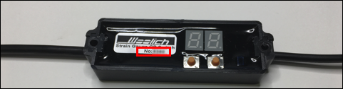
GP Switch sensor - for Quickshifter-only models
GP ASG analogue sensor - for models that have both the Quickshifter and Autoblipper
Here are the tests to complete: - Power test - check that the unit powers up when the ignition is turned on
- GP Switch sensor - for Quickshifter-only models
- The LED display should power on and briefly display two numbers. Pressing the button on the right should show the current sensitivity setting. When the Quickshifter is activated (ie. gear shifter pressed) the LED dot on the right side of the display will turn on briefly.
- If the display shows 'E1' then the sensor has developed a fault and you will need to contact Support
- GP ASG analogue sensor - for models that have both the Quickshifter and Autoblipper
- The red LED should flash once (or twice) when the ignition is turned on. This LED does not turn on when the gear shifter is pressed.
- If the LED stays on after turning on the ignition, then the sensor has developed a fault and you will need to contact Support
If you are not getting any power, then please go through the Race Tools Troubleshooting article for your exact Quickshifter unit using one of the links below: If the voltages seen do not match the test document, please open a support ticket, and let us know the make/model of the bike, and Race Tools ‘type’ as well as the results from the testing doc.
If you have power, then continue as follows: - Check that the clutch switch works correctly.
- Most QS/AB issues are due to the Clutch switch being removed/bypassed/linked/cut.
- The clutch switch must be working correctly for the QS and AB to function correctly.
- The Race Tools functions check the Clutch switch and if the clutch is not being used, then it will trigger the QS/AB. If the Clutch lever is being used, then the QS/AB will not trigger.
- If an option for your model, check that both front and rear wheel speed sensors, are plugged in, and NOT disabled in the bin file settings.
- Some models use the road speed for the Launch Control or Pit Speed Limiter functions.
- If you have the Pit Speed Limiter Harness fitted, make sure the button is NOT pressed.
- The QS/AB will not function when the Pit Speed Limiter button is pressed, as it uses the same signal wire back to the ECU.
- If the gearing (sprockets) has been changed drastically (more than a total of 2-3 tooth difference) then this can affect the ECU’s internal gear calculation (on models that do not have a Gear Position Sensor, like most Yamaha’s).
- Try using stock gearing and see if it then functions correctly.
- You can change the gearing, but there is a limit, at which point the ECU starts getting confused, and the QS/AB may not function as expected.
If you have completed these tests and your issues are still not resolved, please go through the Testing document for your Race Tools type from the Support Center using the two links above, then open a ticket, and report the results to us. Be sure to include your make/model/year, and Race Tools ‘type’.
These Support Center articles may also be of interest to you:
Was this helpful? YesNo
open in new page |
| Diagnosing "You do not have a Race Tools Key" |
To activate any of the Race Tools options (eg. Quickshifter, Autoblipper, etc), you must have purchased a Race Tools package specific for your model of bike. A Race Tools Package includes the Race Tools Hardware like Quickshifter etc, and a software Key (license). If you do not have a Race Tools Key, then you will not be able to activate any of the Race Tools options in the WRT software.
If you open a new bin file in WRT it will have Race Tools turned off by default and no Race Tools Key is needed to write this bin file to the ECU.
If you then turn on Race Tools by activating any of the features (Quickshifter, Pit Speed limiter, etc) in WRT the bin file will now be PERMANENTLY flagged as having Race Tools activated and you will not be able to write it to the ECU without owning/using a dedicated Race Tools Key. Even if you then turn off Race Tools in WRT by disabling Quickshifter etc, the bin file will still be flagged as requiring a Race Tools Key.
If you have already been able to write to the ECU with Race Tools activated, then your Race Tools Key is now locked to this ECU. You can rewrite the ECU as many times as you want with Race Tools turned on or off.
These are the possible reasons this error may appear:
- If you do not have a Race Tools Key but you have activated in the WRT software as described above, you will need to open a new bin file to reset the Race Tools flag.
- If you have received an ECU with Race Tools that was written previously by another tuner, but have not written to this ECU before, you will need to click READ ECU, then use Tools > Request Key Transfer and then Open a Support Ticket.
- Writing over an ECU that has Race Tools activated by another user without requesting a key transfer will erase the Race Tools key in the ECU.
- If you have purchased a Race Tools package including Race Tools Key, but you have not been able to write to the ECU at all, and are seeing the Race Tools Key error message, then please Open a Support Ticket.
- If you see the error message "You do not have a Race Tools Key.." and you have already been able to write to the ECU with Race Tools previously, then it is possible the software is not able to recognize the ECU. This can happen if you have a failed or partial write.
- In this case please open a support ticket explaining the issue, and then READ ECU, and click Tools > Send Bin File to Woolich Racing.
Do not just turn off Race Tools and attempt to write to the ECU again, as this will write over the existing Key we need from your ECU Readout. In this case we will not be able to replace the key and you will be required to purchase a new Race Tools Key.
These Support Center articles may also be of interest to you:
Was this helpful? YesNo
open in new page |
| Quickshifter-only Hardware Testing |
This information is about testing the Race Tools hardware for the Quickshifter-only GP Switch sensor. Note that there is no Autoblipper function with this hardware. This article refers to the one with the 2-digit LED display and the two push buttons.
GP Switch sensor - for Quickshifter-only models
Please open the User Guides and Installation Manuals, and scroll down to the Race Tools Installation Guides. There will be a Race Tools Troubleshooting Guide listed directly under your model's Race Tools installation guide, for most of the different types of Race Tools.
Please follow along with the guide and complete the testing detailed in that document.
If your results match those described in the troubleshooting guide then the hardware is working as expected (ie. there is no problem with the hardware).
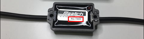
If your results do not match the troubleshooting guide (ie: there is no initial voltage, or there is no change when doing the tests), then please Open a Support Ticket, and let us know the model/year, your Racetools Serial Number, and the results of the above test.
These Support Center articles may also be of interest to you:
Was this helpful? YesNo
open in new page |
| Quickshifter/Autoblipper Hardware Testing |
This information is about testing the Race Tools hardware for the Quickshifter/Autoblipper unit.
Plug the Race Tools Harness into the bike harness as per normal operation. Turn the Ignition ON.
Use a multimeter to measure sensor signal voltage at the connector that attaches the Race Tools to the Bike harness. (O2 or EXUP plug) - Race Tools Brown wire - Ground (Black multimeter probe) - Race Tools White wire - Signal (Red multimeter probe)
A) No Load Voltage Test - No load signal voltage = 2.5V ± 0.15V - Write down this voltage reading (Value A) - Voltage should be fairly stable
B) Compression Load response - Put compression force on sensor - Signal voltage should move towards 5V - Write down this voltage reading (Value B) - Release force from sensor - Voltage should return to 2.5V ± 0.15V
C) Tension Load response - Put tension force on sensor - Signal voltage should move towards 0V - Write down this voltage reading (Value C) - Release force from sensor - Voltage should return to 2.5V ± 0.15V
D) Pit Speed Limiter button response (if available) - Press the PSL button ON - Record the signal voltage seen - Write down this voltage reading (Value D) - Press the PSL button OFF - Voltage should return to 2.5V ± 0.15V
Potential problems when testing the Quickshifter/Autoblipper voltages. The Quickshifter sensors and controllers have an auto-zero feature built into them which can sometimes interfere with these voltage tests. When no pressure is applied to the sensor, it self-zeroes in its current state which is typically about 2.5V. The sensor then waits for a change from this value in order to detect an up- or downshift.
When you apply pressure, the controller detects the CHANGE in voltage and triggers the output. If the pressure is applied for more than 3-4 seconds, the sensor begins to self-zero again, and you will see the voltage output return to the 'no pressure state', if you then release the pressure, the controller again detects the change (from the new zero state) and triggers the output in the other direction. It then begins to zero itself again.
So, if you put pressure on the shift sensor for more than 3-4 seconds it will skew the results. If you are using a digital multimeter, remember they can be relatively slow to respond and display voltages, and it can be more difficult to see the voltages in the 3-4 second window accurately.
If your results match the above, then the hardware is working just fine.
If your results do not match the above (ie: there is no initial voltage, or there is no change when applying pressure), then please Open a Support Ticket, and let us know the model/year, your Race Tools serial number, and the results of the above tests.
Was this helpful? YesNo
open in new page |
| Quickshifter - Configuration in WRT Software |
The Woolich Racing Quickshifter allows shifting up through the gears without using the clutch by momentarily cutting the engine by either killing the ignition and/or stopping the delivery of fuel. Cutting the engine stops torque production allowing gear changes to be made without needing to use the clutch, and can minimize wear on the gearbox. Setting up a Quickshifter correctly requires installation of the hardware onto the bike as well as configuring the Quickshifter inside the Woolich Racing Tuned software (WRT) and finally writing the new settings to the ECU. Each Quickshifter has it's own specific installation manual for connecting to the specific model of bike, these are found on the User Guides & Installation Manuals page.
The Race Tools configuration is started by clicking on the Race Tools button as shown below: Quickshifter configuration options for a 2020 Yamaha YZF-R1
Configuration of the Quickshifter involves the following steps: - Place a tick in the 'Enable Quickshifter' checkbox
- Clearing this checkbox disables the Quickshifter
- Select your Shift Direction
- This enables you to choose between bikes with a normal shift pattern and those with a reverse (race) shift pattern
- Set the Activation Pressure
- The Activation Pressure is the minimum pressure required to initiate an engine cut during gear shifting
- The default setting is 3 and this works well for most bikes
- Reducing the number requires less pressure to activate (1 is the softest setting)
- Increasing the number requires higher pressure to activate (10 is the hardest setting)
- Set the 'Delay Between Shifts'
- The 'Delay Between Shifts' is the minimum time between engine cuts in milliseconds
- This is referred to as 'Next Shift Delay' in some prior versions of Race Tools
- After the Quickshifter sensor is triggered the engine is cut and the bike shifts up a gear. The sensor will not trigger another engine cut until the 'Delay Between Shifts' has elapsed.
- Using a value under 100ms will result in a higher risk of a ‘double cut’ where the engine will cut twice in a row.
- The default is 300 ms
- Ignition Cut and Fuel Cut
- On some models it is possible to choose to use an Ignition Cut and/or Fuel Cut as shown below for a 2020 Honda CBR600RR
- At least one of these options MUST be selected for the Quickshifter to function. If neither is selected then the engine will not be cut during shifting, risking damage to the gearbox.
- Selecting Ignition Cut will kill the ignition when the Quickshifter is activated. If Ignition Cut is not selected, the spark plugs will still spark inside the cylinders.
- If Fuel Cut is selected, then fuel will not be injected into the cylinders during the engine cut. If Fuel Cut is not selected, then fuel will still be injected into the cylinders even if there is no spark.
- Selecting Ignition Cut with no Fuel Cut can potentially increase pop and bang during shifting
- The Quickshifter will only function if at least one of these options is selected.
Quickshifter Maps Quickshifter maps display the engine cut times in milliseconds used for each gear shift dependent on engine RPM (row titles) and throttle position sensor (TPS, column titles).
Sample Quickshifter map for a 2020 Honda CBR600RR
If you click the ‘Gear’ dropdown menu, you can select the gear transition that you wish to view the cut time map for. The ‘Gear Unknown’ map is used when the ECU cannot determine which gear the bike is currently running in.
These maps can be used to make fine adjustments to the Quickshifter performance to achieve smooth shifts for different conditions. The preset values have been carefully set for each model of bike so care should be taken when making changes to these maps.
Was this helpful? YesNo
open in new page |
| Quickshifter - Tuning Quickshifter Maps |
Quickshifter maps display the engine cut times in milliseconds used for each gear shift dependent on engine RPM (row titles) and throttle position sensor (TPS, column titles).
If you click the ‘Gear’ dropdown menu, you can select the gear transition that you wish to view the engine cut times for. The ‘Gear Unknown’ map is used when the ECU cannot determine which gear the bike is currently running in.
'Gear transition' dropdown menu for a 2022 Yamaha YZF-R6
These maps can be used to make fine adjustments to the Quickshifter kill time to achieve smooth shifts for different conditions. The preset values have been carefully defined for each model of bike so care should be taken when making changes to these maps. The standard Quickshifter maps are usually good for most rider/bike combinations and should only be changed if the gear changes are not smooth.
These Support Center articles may also be of interest to you:
Was this helpful? YesNo
open in new page |
| Quickshifter - How to Change Between Standard and Race Shift Patterns |
GP Switch sensor (Quickshifter-only):
The Woolich Racing Quickshifter GP Switch detects gear shifts and momentarily cuts the engine. The Quickshifter GP Switch model does not distinguish between up-shifts and down-shifts so it only used as a Quickshifter for shifting up through the gears. The Quickshifter GP Switch does not work as an Autoblipper. This method enables you to choose between bikes with a normal shift pattern and those with a reverse (race) shift pattern. - Turn the ignition off so that the Quickshifter is powered off
- Hold down both buttons on the Quickshifter module
- While holding both buttons down, turn the ignition on
- The LED's will first show some numbers (firmware version) and will then show the letters “UP” as shown in the image below
 - Release the two buttons and the letters 'UP' will flash indicating that the unit is ready to read the shift direction
- Apply and hold pressure on the Gear Shift lever in the upshift direction e.g. if the bike is in 2nd gear, apply pressure in the direction of 3rd gear, hold the pressure until the small LED dot blinks once and the LED display then turns off
- The Quickshifter should now be configured for the correct “UP” shift direction.
- You can test the activation by applying pressure to the gear shift lever, a small dot on the Quickshifter LED display will light up when the pressure applied initiates a shift.
ASG Sensor (Quickshifter and Autoblipper):
For all models using the ASG sensor you either can set the shift direction directly in the software, or you can set it manually through the sensor. You only need to complete this using ONE of these methods.
Method A: Changing the setting in the bin file
You can set the shift direction in the Race Tools section of the bin file. For some models you may find this in the 'Advanced Settings' instead. This method requires you to write to the ECU.
Method B: Manual Shift direction instructions
This complete procedure from 3 to 6 needs to be completed within 15 seconds, otherwise the configuration will be interrupted and the set up needs to be done again. This method does not require you to write to the ECU.
IMPORTANT. This procedure shall only be done with the ignition switched ON, engine NOT running.
1. Install the Quickshifter. 2. Switch on the ignition of the bike. Do not start the engine. 3. The LED flash 1 or 2 times depending on which shift direction is set. 4. Directly after the LED go out, push and hold the gear lever in the direction you want the Shift direction until the LED flashes rapidly. This indicates that the Quickshifter is in ‘Configuration Mode’ for setting up the Up Shift direction. 5. Push the gear lever at least 5 times in a ‘pulse’ movement in the same direction as in step 3, the Shift direction. 6. Directly after step 5, push and hold the gear lever in the same direction for 3 seconds. The LED will go out, and then flash 1 or 2 times depending on which shift direction is set.
The Upshift direction is now set.

These Support Center articles may also be of interest to you:
Was this helpful? YesNo
open in new page |
| Launch Control - How to Use |
Launch Control is a feature in Woolich Racing Race Tools which allows quick launching of the bike from a standstill in a controlled and reproducible manner. All that the rider needs to control on the bike is the release of the clutch, throttle control is automatic as per the configuration detailed below. It does this by first limiting the engine launch RPM and controls the ramp of acceleration in first gear. If the bike changes gear or the clutch is re-engaged, the launch will be deactivated.
Disclaimer: Woolich Racing Launch Control DOES NOT control the clutch actuation or provide any sort of wheelie or traction control that does not already exist on the bike. When using Launch Control it is important to remember that the rider still needs to control the clutch, and that Launch Control will not prevent a motorcycle from lifting the front wheel.
Launch Control of the bike is activated when the bike is in first gear and either at a standstill or traveling at < 10 km/hr with the clutch in. After the 'Launch Delay' time the engine RPM is lowered to the 'Launch RPM', the bike (ECU) then waits for the clutch to be disengaged and starts to ramp the engine RPM, the RPM will increase until one of the following conditions is met: - Max Ramp RPM or Release Speed is reached (depends on model)
- Clutch lever is pulled in
- Gear shifter activated (ie. change from 1st gear)
This is illustrated in the graph below: Launch Control may be purchased as part of a Race Tools package or as a standalone item, Launch Control does not require installation of any hardware onto the bike except for those needed to write the settings to the ECU (eg. harnesses and communications interface). Setting up Launch Control correctly then only requires activating the Launch Control inside the Woolich Racing Tuned software (WRT) and finally writing the new settings to the ECU.
Each Race Tools package has it's own specific installation manual for connecting to the specific model of bike, these are found on the User Guides & Installation Manuals page. The various model-specific options for Launch Control are detailed in these manuals.
Was this helpful? YesNo
open in new page |
| When are you making Race Tools for my Bike? |
Woolich Racing is continually developing our product offering including the models of bikes with Race Tools supported. The development of Race Tools hardware and software for a specific bike is a time-intensive exercise and requires considerable hands-on time with the actual bike.
The ongoing Race Tools model support is then driven by how popular a request is, whether the Woolich Development Team have time to invest in that model, and whether we have a bike available for testing.
In short Woolich Racing does not develop Race Tools for every model of bike, but rather only those that are in demand and we can see there is a significant market for it.
If you would like to request that Race Tools be developed for your specific model, you are welcome to open a Support Ticket and let us know your model/year. We will add your email address to the waiting list for the specific model so that we can notify you of future developments including if Race Tools is released for this model.
We are unable to provide you with any sort of time frame and/or confirmation about if/when Race Tools will be developed for your model. We will however always strive to increase our support for new models and can keep you notified accordingly.
These Support Center articles may also be of interest to you:
Was this helpful? YesNo
open in new page |
| Kawasaki Race Tools and Harnesses |
Woolich Racing has offered Race Tools packages for Kawasaki models for many years and there are currently more than 10 different Race Tools packages which have been customised for specific models. The Race Tools kits typically include a Quickshifter or Quickshifter/Autoblipper and a harness which connects the sensor to the bike. In recent years Kawasaki has made changes to some of their bikes, moving from a single O2 sensor in the exhaust to having two O2 sensors, one in front of- and one behind the catalytic converter. This has been observed on several Kawasaki models with Denso ECUs, such as Z400, Z650, Z900, Z900RS as well as the complete Ninja range typically using the Kawasaki Race Tools Type 9, 11, and 12. This change has required us to modify our Race Tools for these models, this article explains how to select the correct Race Tools kit and for your Kawasaki model. The Race Tools harnesses provide 12V and ground to power the sensor, and the signal generated by the sensor is connected back to the ECU by using either the exhaust servo or oxygen (O2) sensor, depending on the model. The 2021 Z400 has a single oxygen sensor and uses a Kawasaki Race Tools Type 11 which connects to the oxygen sensor plug as shown below. 
Rear view of O2 Sensor Plug for Kawasaki Race Tools 11 (note that locking tab is on the top) Recent models of Z400 (eg. 2023) are equipped with two oxygen sensors which have different wiring compared with previous models, and so require a different harness in order to connect the O2 sensor plug. These newer models have one O2 sensor located in front of the catalytic converter and another located behind it. The Race Tools harness for these models with two O2 sensors connects to the front O2 sensor and the plug wiring is shown below.  Rear view of Kawasaki Race Tools 12 O2 Sensor Plug (note that locking tab is on top) The connection of the Race Tools harness O2 plug to the bike O2 plug is shown below:
Rear view of Bike O2 Sensor Plug for Kawasaki Race Tools 12 (note that locking tab is on the top) The location of the green wire on the Race Tools plug should correspond with the blue/yellow wire on the bike, and the red wire should correspond with the brown/white wire.
These Support Center articles may also be of interest to you:
Was this helpful? YesNo
open in new page |